Phototropic Origami Pavilion:
A Prototyped E-textile Composite
Term Pennsylvania State University Spring 2018
Course LArch 497 Soft Build
Instructor Felecia Davis
Partner Julian Huang, Jjimi Demi-Ajayi
The project started with the research question of whether one make a responsive fiber composite where electronics are embedded into the fabric? Later developed into a responsive textile by embedding conductive and resistive yarns into a fiberglass knit to initiate a responsive project. The innovation resides in the introduction of simple electronic components to make an e-textile.
Learn more about this project at: Photropic Pavilion (click me)
The project is exhbit at: Intersection Exhbition (click me)
Penn State: Stuckeman School participates in Textile Intersections conference in London (click me)
ASCA Conference: (click me)
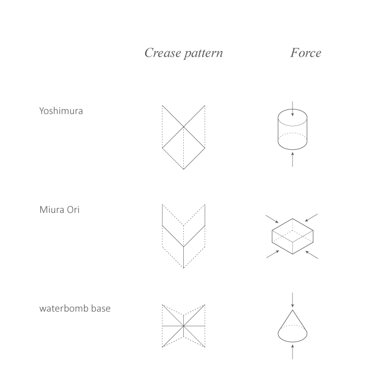

Diagram: Yoshimura, Miura Ori, Waterbomb, Diagnal, Kresling, Resch
1.0
CREASE PATTERN
The flat-packed structure not only allows easy transportation, but it also allows possibilities to generate various shapes within the same crease pattern. During the early stages of the project, we looked into different crease patterns.

2.0
EXPERIMENTATION
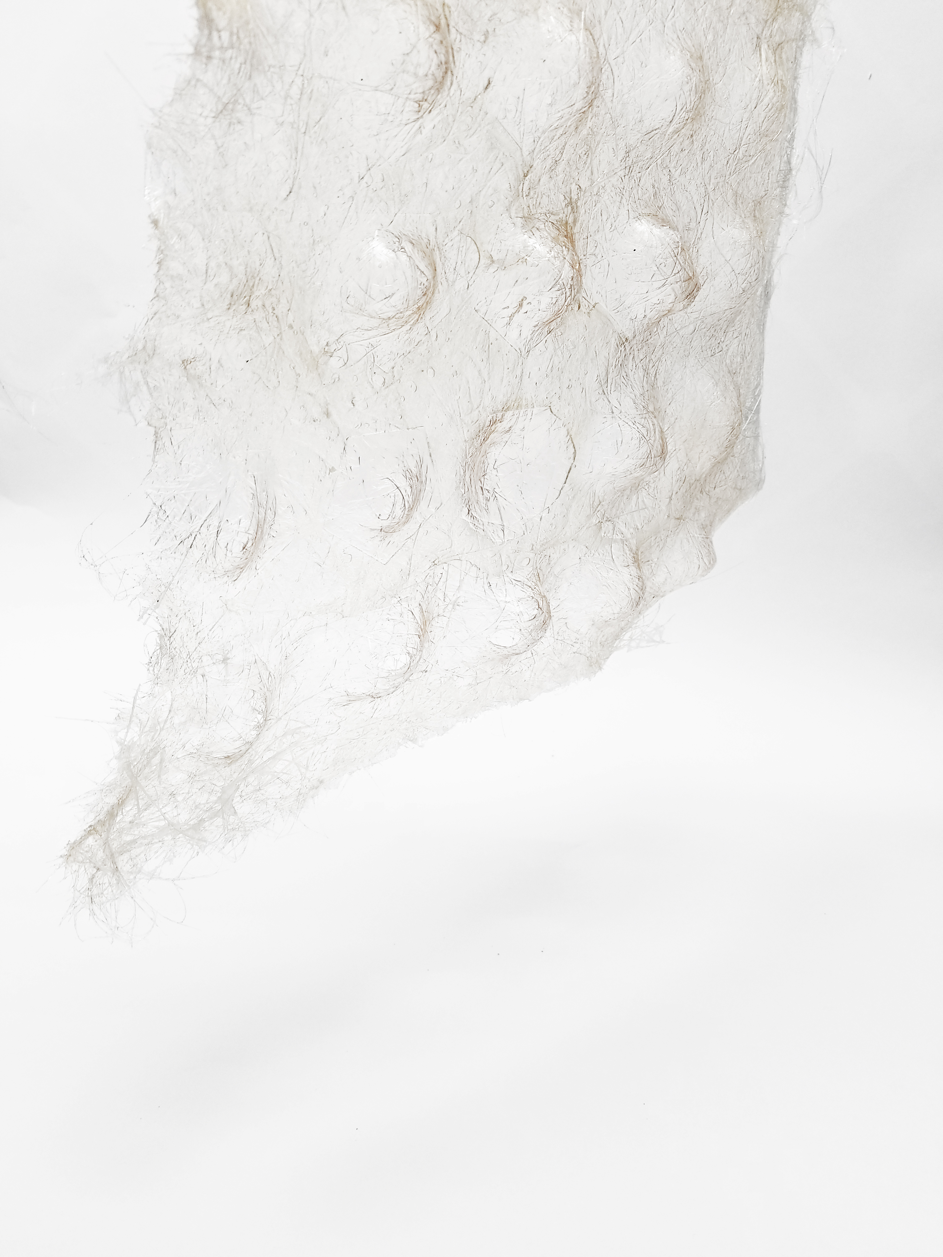
During the earlier phase of the project, we conducted preliminary material testing on fiber glass using a different range of methods. The experiments help to understand the material properties and later inform the final fabrication methodology selected for the project. The experiments were divided into two parts, first to test how to form the desired shapes through different types of molds, and latter to investigate particularly on the developing techniques to work with origami folding pattern.


3.0
EXPERIMENTATION
EXPERIMENTATION
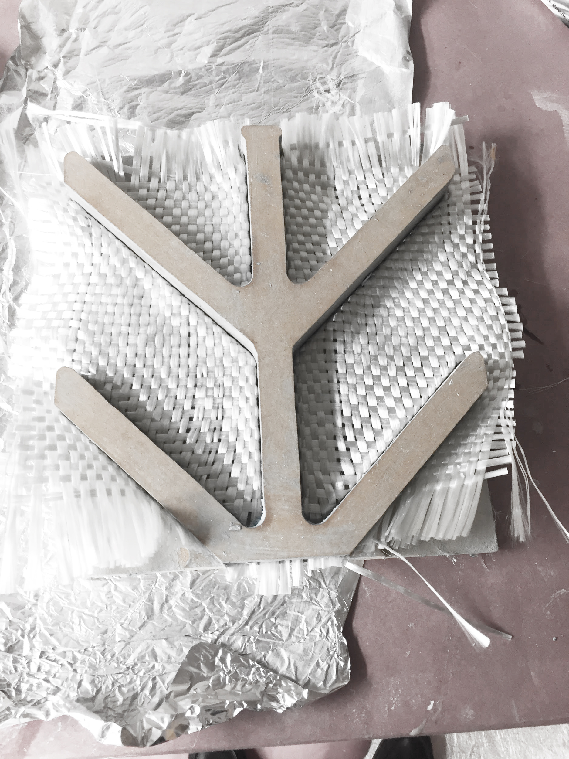
Examples of the initial methods are using different fabrication techniques to make molds to shape fiber glass sheets into desired forms, and to use stencils to inform new shapes through behaviors of pulling the materials or gravity.
1. Apply resin through syringe onto the fiberglass sheet with laser-cut stencil on top.
The resulted crease pattern is not sharp, since the stencil only provide guidance for the location of applying resin, yet it does not provide enough boundary for blocking out unwanted resin on the crease line.
2. Apply resin onto the fiberglass sheet with a CNC-milled positive and negative mold of one module of the 2D crease pattern in the flat form.
The resulted crease pattern is sharper than the previous experiment. However, due to the limitations of CNC miller and the nature of positive and negative molds, the crease line is restricted to a minimum size that is considered too large for the scale of the structure. Hence, the application of using the molds repetitively or milling larger molds with more modules are not practical.
3. Apply resin onto the fiber glass sheet with a CNC-milled mold of one module of the 3D crease pattern in the folded form. The resulted pattern crease pattern is not sharp enough for the folding behavior, the fiber glass sheet is resolved in a folded form due to the mold, and the application of CNC mold is not practical.
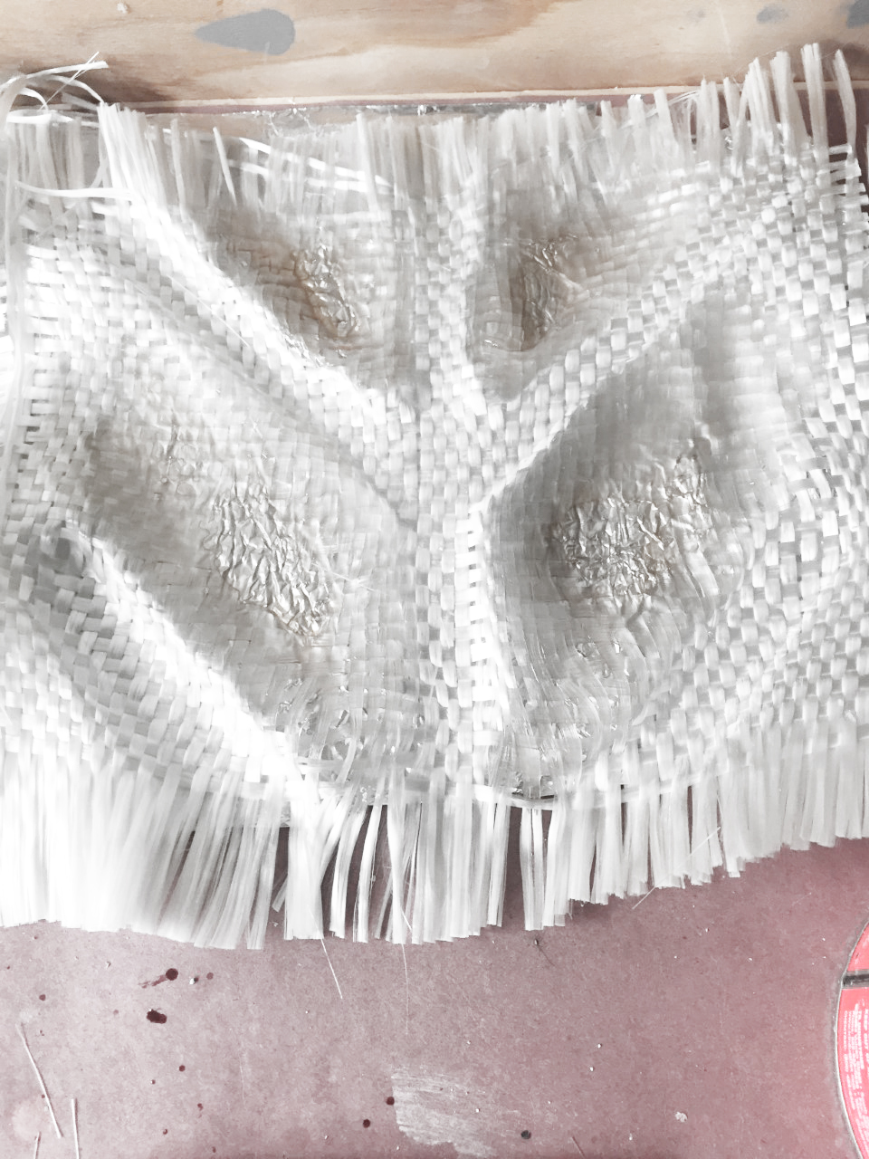
4. Apply resin onto the fiber glass sheet with crease pattern being tapped directly on the material.
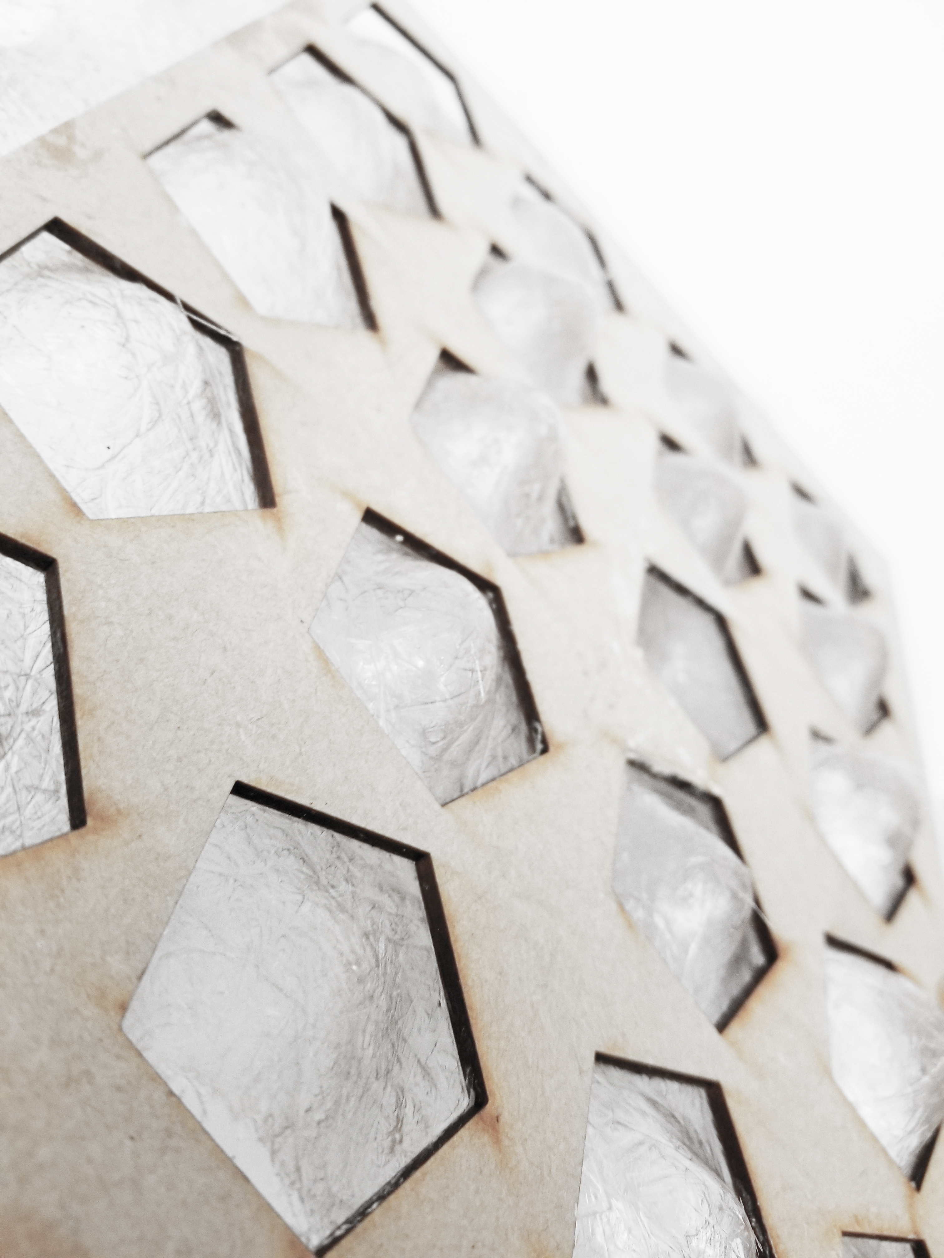
The resulted creased pattern is the sharpest of all the experiments, since the tapes provide enough boundary to block out unwanted resin on the crease line. The application of taping fiber glass sheet through a printed stencil is efficient and economical. The use of tape also allows enough flexibility to control of the size of the crease line that is not covered by resin. We con- cluded the taping mechanism is desired to apply resin to the planar portions of the structure, and the molding mechanism is desired to apply resin to the solid portions of the structure.
The resulted crease pattern is not sharp, since the stencil only provide guidance for the location of applying resin, yet it does not provide enough boundary for blocking out unwanted resin on the crease line.
2. Apply resin onto the fiberglass sheet with a CNC-milled positive and negative mold of one module of the 2D crease pattern in the flat form.
The resulted crease pattern is sharper than the previous experiment. However, due to the limitations of CNC miller and the nature of positive and negative molds, the crease line is restricted to a minimum size that is considered too large for the scale of the structure. Hence, the application of using the molds repetitively or milling larger molds with more modules are not practical.
3. Apply resin onto the fiber glass sheet with a CNC-milled mold of one module of the 3D crease pattern in the folded form. The resulted pattern crease pattern is not sharp enough for the folding behavior, the fiber glass sheet is resolved in a folded form due to the mold, and the application of CNC mold is not practical.
4. Apply resin onto the fiber glass sheet with crease pattern being tapped directly on the material.
The resulted creased pattern is the sharpest of all the experiments, since the tapes provide enough boundary to block out unwanted resin on the crease line. The application of taping fiber glass sheet through a printed stencil is efficient and economical. The use of tape also allows enough flexibility to control of the size of the crease line that is not covered by resin. We con- cluded the taping mechanism is desired to apply resin to the planar portions of the structure, and the molding mechanism is desired to apply resin to the solid portions of the structure.

4.0
CIRCUIT
CIRCUIT
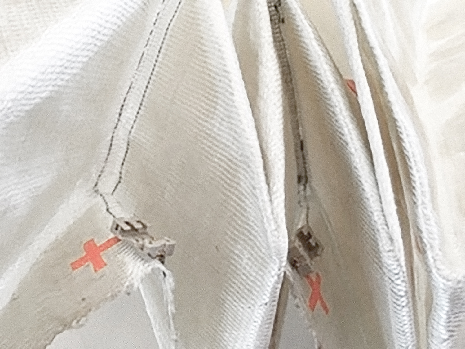
The phototropic structure uses triaxial stitched fiberglass at 36 oz./yard, which is a high strength fabric. Two pieces make up its parts each 3’ -4” [101.6cm] wide and 10’ -0” [304.8cm] in height. A fast curing polyester resin was used to make the structure. The team also worked with a soybean based resin that worked equally as well for these purposes but did not produce the same translucency in the coated fab ric. Duct tape was sturdy enough to withstand curing resin.
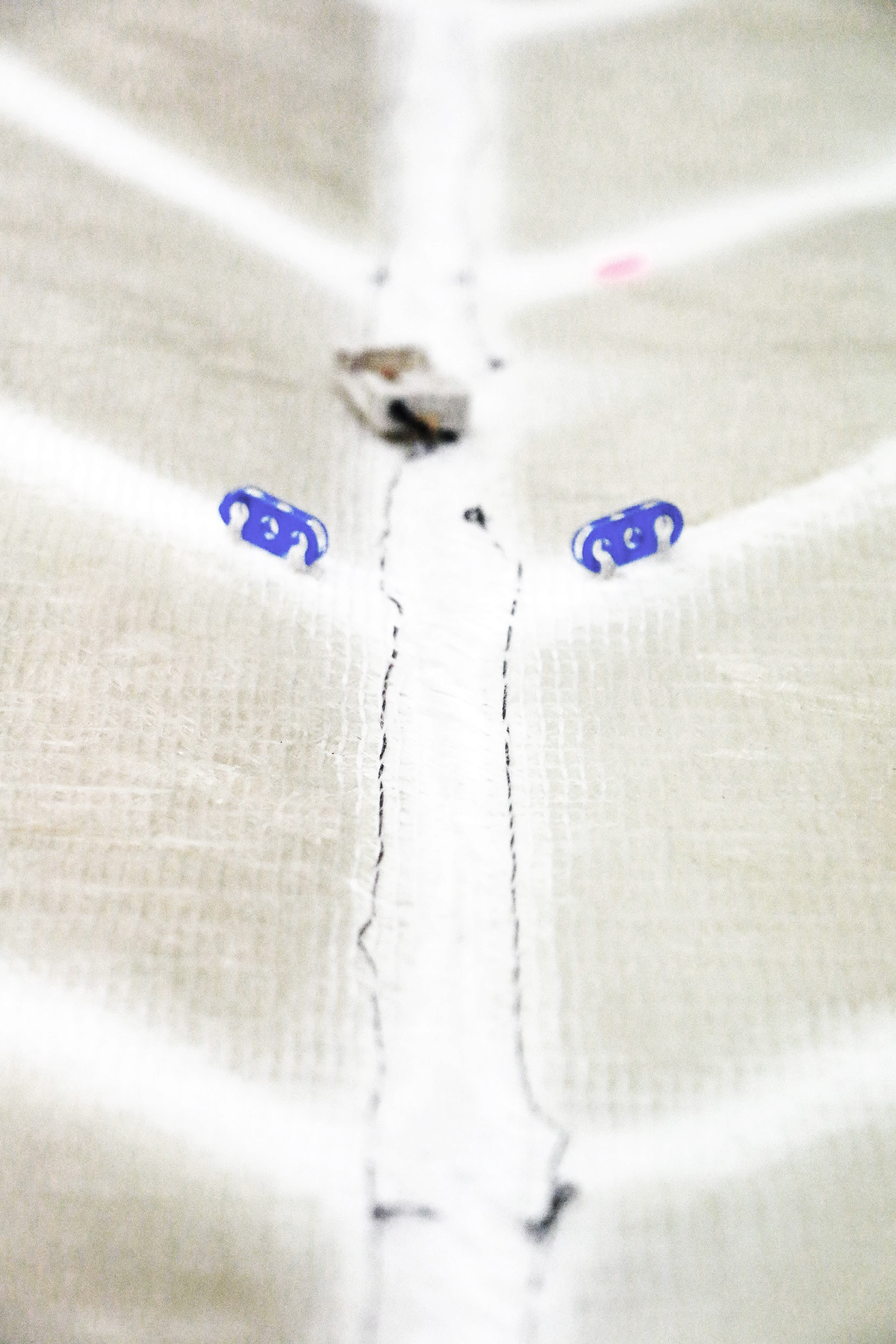
Circuit materials included 4-ply stainless steel coated conductive thread, coin cell battery holders, 3-volt coin cell batteries, small LED’s and an Arduino board, a breadboard with a photosensor.
Lasercut buttons from plexiglass were used to gather the folds of the material in tension. Monofilament line was used to place the folds under tension.

5.0
IMPLEMENTATION
IMPLEMENTATION
The second part of this research is to consider the manufacturing techniques of the E-textile in the industrial context. The goal is to create conductive fiber composites that allow designers to implement responsive mobile structures, and to consider the relationship between the form and to the material itself.
We propose to add either conductive yarns or resistive yarns to the Vectorply Corp. machines. The process is not only straightforward but also functional to turn the fabric into conductive materials. Conductivity is an especially useful property for the designers to consider structural aspects of their designs, such as providing messages regarding the failure or success of the built object. Alternatively, in this case, transforming external information into directions for the shape changes. The process not only transforms the fiber composites into materials with a built-in strain sensor but also opens the opportunities to allow fiber composites to connect to the Internet of Things.
We propose to add either conductive yarns or resistive yarns to the Vectorply Corp. machines. The process is not only straightforward but also functional to turn the fabric into conductive materials. Conductivity is an especially useful property for the designers to consider structural aspects of their designs, such as providing messages regarding the failure or success of the built object. Alternatively, in this case, transforming external information into directions for the shape changes. The process not only transforms the fiber composites into materials with a built-in strain sensor but also opens the opportunities to allow fiber composites to connect to the Internet of Things.
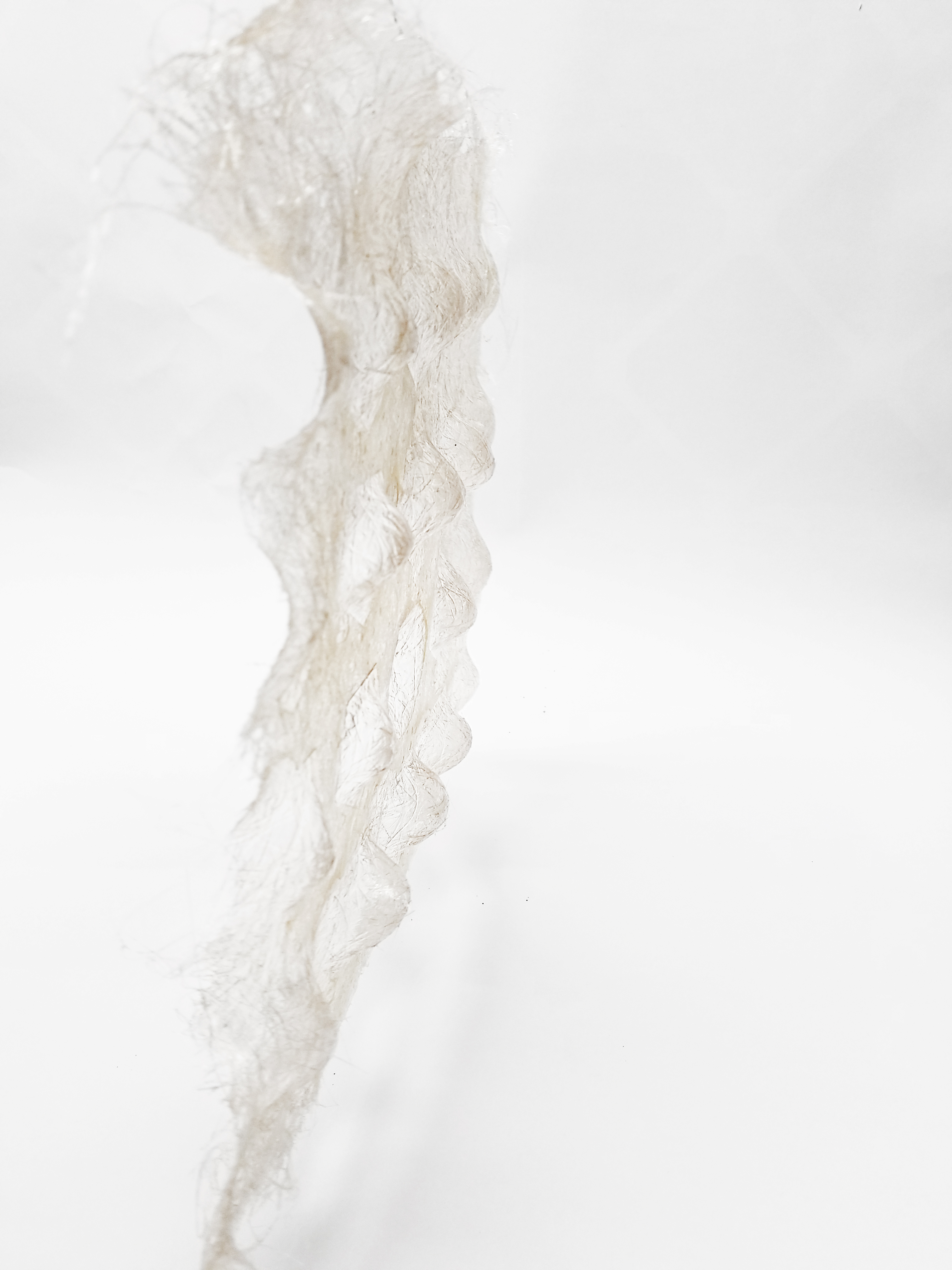
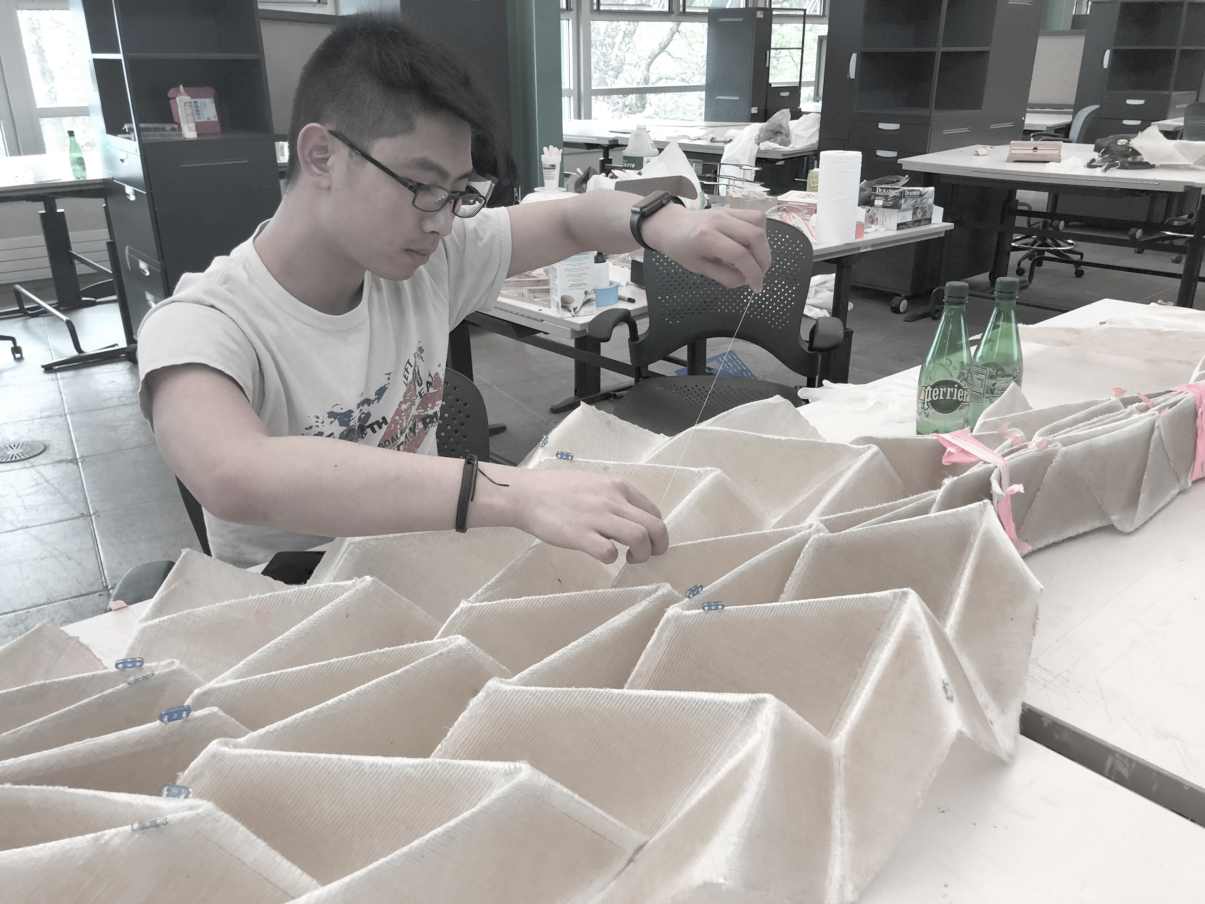
during the process
more, during the process...
(fold, fold, and fold)

and then, time to assemble

during the night time
and of course,
during the day time